7. The board
This chapter introduces the board, its hardware and how to boot it.
7.1. Hardware
The hardware documentation of ZedBoard can be found here:
7.2. Power-On
The board is shipped with an external power adapter with two different socket adapters.
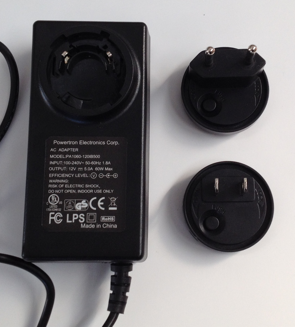
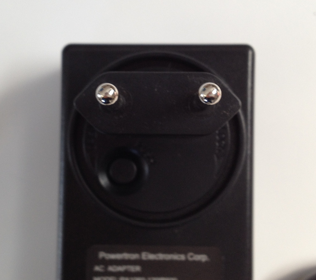
Sort out the socket adapter that is right for you. Place it properly.
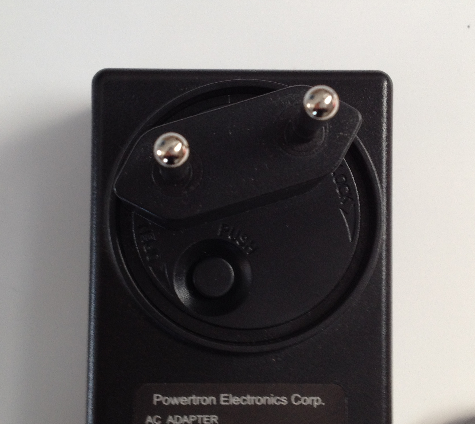
Push it and rotate it clockwise until you hear a slight click.
To power-on the board, just connect the external power adapter to ZedBoard connector J20 and move switch SW8 to the “On” position.
7.3. Serial Console
On ZedBoard there is an USB-UART port (J14) labeled UART
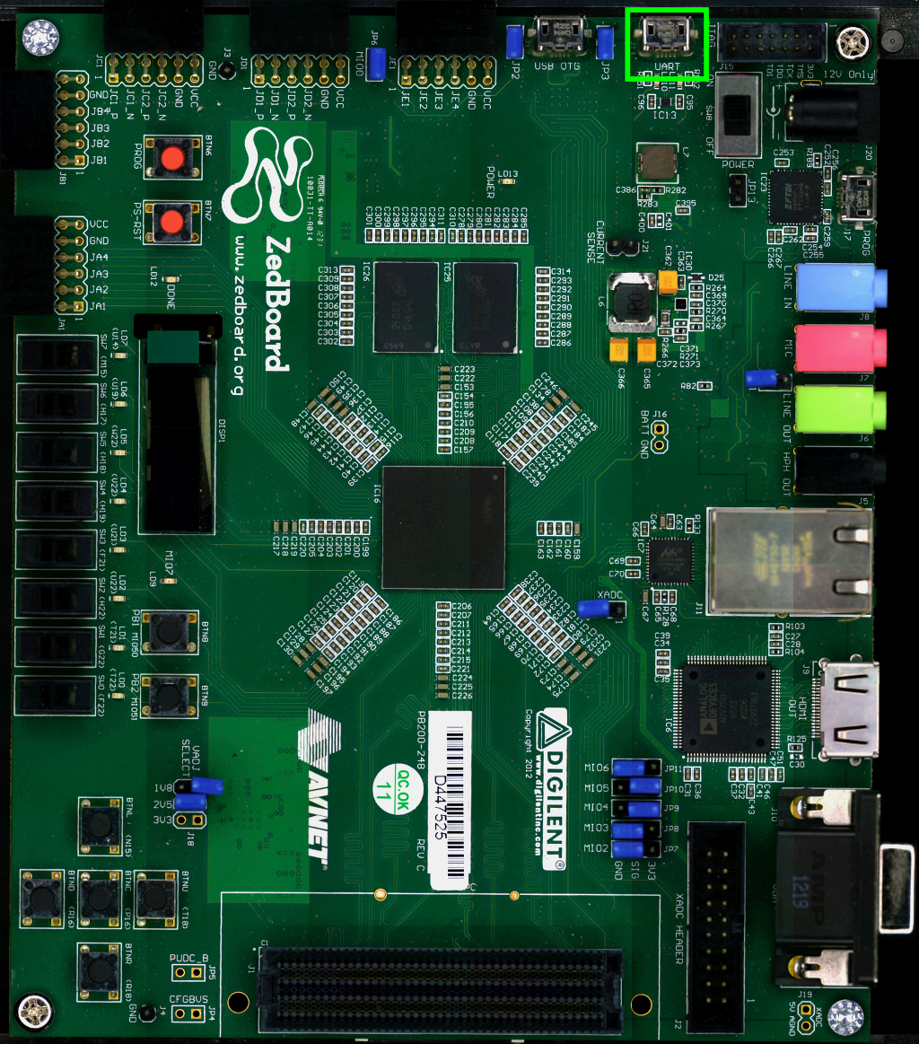
which you can connect, by means of a micro-USB cable, to your personal computer.
Note
Every operating system has its own killer application to give you a serial terminal interface. In this guide, we are assuming your host operating system is Ubuntu.
On a Linux (Ubuntu) host machine, the console is seen as a ttyACMX device and you can access to it by means of an application like minicom.
Minicom needs to know the name of the serial device. The simplest way for you to discover the name of the device is by looking to the kernel messages, so:
- clean the kernel messages
sudo dmesg -c- connect the mini-USB cable to the board already powered-on
- display the kernel messages
dmesg- read the output
[29629.785374] usb 3-2: >new full-speed USB device number 4 using xhci_hcd
[29629.806908] usb 3-2: >New USB device found, idVendor=04b4, idProduct=0008
[29629.806915] usb 3-2: >New USB device strings: Mfr=1, Product=2, SerialNumber=4
[29629.806919] usb 3-2: >Product: Cypress-USB2UART-0123456
[29629.806922] usb 3-2: >Manufacturer: 2012 Cypress Semiconductor
[29629.806925] usb 3-2: >SerialNumber: 0201258B0816
[29629.858654] cdc_acm 3-2:1.0: >This device cannot do calls on its own. It is not a modem.
[29629.858705] cdc_acm 3-2:1.0: >ttyACM0: USB ACM device
[29629.859345] usbcore: registered new interface driver cdc_acm
[29629.859347] cdc_acm: USB Abstract Control Model driver for USB modems and ISDN adapters
As you can see, here the device has been recognized as /dev/ttyACM0.
Now that you know the device name, run minicom:
sudo minicom -wsIf minicom is not installed, you can install it with:
sudo apt-get install minicomthen you can setup your port with these parameters:
+-----------------------------------------------------------------------+
| A -    Serial Device      : /dev/ttyACM0                              |
| B - Lockfile Location     : /var/lock                                 |
| C -   Callin Program      :                                           |
| D -  Callout Program      :                                           |
| E -    Bps/Par/Bits       : 115200 8N1                                |
| F - Hardware Flow Control : No                                        |
| G - Software Flow Control : No                                        |
|                                                                       |
|    Change which setting?                                              |
+-----------------------------------------------------------------------+
        | Screen and keyboard      |
        | Save setup as dfl        |
        | Save setup as..          |
        | Exit                     |
        | Exit from Minicom        |
        +--------------------------+
If on your system the device has not been recognized as /dev/ttyACM0, just replace /dev/ttyACM0 with the proper device.
Once you are done configuring the serial port, you are back to minicom main menu and you can select exit.
7.4. Let’s boot
To properly boot the board, you need several components:
- an SD card,
- file BOOT.BIN,
- the Linux kernel image,
- the device tree blob,
- a bootscript, and
- a root file system.
This section will guide you through all that stuff.
7.4.1. SD card
The SD card has to be prepared with two partitions:
- a FAT16 partition able to contain the following files: BOOT.BIN, uEnv.txt, uImage and devicetree.dtb. 64MB will be more than enough
- an EXT2 partition to contain the root file system
The SD card has to be inserted in J12.
Furthermore, on the board there is a set of switches related to the boot process. Verify ZedBoard boot mode (JP7-JP11) and MIO0 (JP6) jumpers are set like in the following picture:
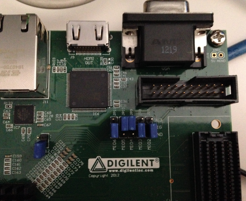
that means boot from SD card, as described in the Hardware User Guide:
7.4.2. BOOT.BIN
To boot the board, the first thing you should care about is the boot file. The boot file is composed by up to three components:
- a First Stage BootLoader,
- a valid Bitstream (this is optional), and
- u-boot.
Its name is BOOT.BIN.
This guide won’t treat the creation of the Bitstream and the First Stage BootLoader. For information about those components, please refer to Xilinx’s official documentation:
A guide on how to prepare file BOOT.BIN is available here:
This SDK relies on a pre-generated BOOT.BIN, which can be downloaded from here:
BOOT.BIN has to be copied in the first partition of the SD card you use to boot the board.
7.4.3. Kernel
Yocto generates the Linux kernel image ready to be deployed on the board when you build virtual/kernel or an image (see Bitbake Section for more information on how to use Bitbake). You will find it inside directory:
/home/architech/architech_sdk/architech/zedboard/yocto/build/tmp/deploy/images/zedboard/uImageuImage has to be copied to the first partition of the SD card.
7.4.4. Device Tree
The Flattened Device Tree (FDT) is a data structure for describing the hardware in a system. It is a derived from the device tree format used by Open Firmware to encapsulate platform information and convey it to the operating system. The operating system uses the FDT data to find and register the devices in the system.
The Device Tree Source (.dts) file is a text file containing the specification. The Device Tree Blob file (.dtb) is the blob version of the source one, and it is passed to the Linux Kernel at boot.
You can get the Device Tree Blob file from here:
You can get the corresponding Device Tree Source from here:
7.4.5. Bootscript
With our flow, the default settings of u-boot will cause the Linux boot process to fail. You need to customize it by means of a file named uEnv.txt with these commands in it:
bootcmd=fatload mmc 0 0x3000000 uImage; fatload mmc 0 0x2A00000 devicetree.dtb; bootm 0x3000000 - 0x2A00000
uenvcmd=boot
Important
Make sure uEnv.txt is terminated by an empty line.
If you prefer, you can download file uEnv.txt from here:
u-boot will look for uEnv.txt automatically at boot.
uEnv.txt has to be copied to the first partition of the SD card.
7.4.6. RootFS
Every time you build an image recipe with Bitbake you get a root file system. All the built root file systems are stacked under directory:
/home/architech/architech_sdk/architech/zedboard/yocto/build/tmp/deploy/images/zedboard/To deploy the root file system, clear the second partition of the SD card and untar the root file system tarball Yocto generated directly to the second partition of the SD card.
7.4.7. Compose the SD card
Warning
The following instruction will make you overwrite your SD card content, it will be lost forever! If you have important data on it, make sure you do a backup of your data on the SD card before catching up with the next steps.
To sum up, the first time you create your SD card, create two partitions on it. The first one has to be a FAT16 (name it boot), 64MB will be more than enough. Create the second partition as an EXT2 (name it rootfs), make it big enough to fill the free space on the disk size.
You are going to need the following files: BOOT.BIN, uEnv.txt, uImage, devicetree.dtb, <image>-zedboard.tar.gz. <image> is the recipe name used to build your image, for example: core-image-minimal-dev, so that the rootfs tarball name would be core-image-minimal-dev-zedboard.tar.gz.
Now, we assume that the first partition of the SD card gets mounted (in your SDK virtual machine) under:
/media/bootwhile the second partition gets mounted under:
/media/rootfsWarning
If that’s not the case for your configuration, please find out which are the proper mounting points for those two partitions on your system and replace them in the following instructions.
Furthermore, we assume you previously downloaded files BOOT.BIN, uEnv.txt, and devicetree.dtb inside directory:
/home/architech/Documents/zedboardOk then, we can finally deploy bootloader and kernel on the first partition of the SD card:
cp /home/architech/Documents/zedboard/BOOT.BIN /media/boot/
cp /home/architech/Documents/zedboard/uEnv.txt /media/boot/
cp /home/architech/Documents/zedboard/devicetree.dtb /media/boot/
cp /home/architech/architech_sdk/architech/zedboard/yocto/build/tmp/deploy/images/zedboard/uImage /media/boot/
and the root file system on the second partition of the SD card:
sudo rm -rf /media/rootfs/*
sudo tar -xzf /home/architech/architech_sdk/architech/zedboard/yocto/build/tmp/deploy/images/zedboard/<image>-zedboard.tar.gz -C /media/rootfs/
If you just need to install a new root file system on your SD card, you can execute just the last step.
7.5. Network
The network PHY is provided by Marvell’s chip 88E1518. Within Linux, you can see the network interface as eth0.